カラーOLED SSD1331
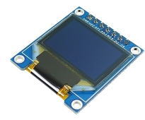 有機ELディスプレイ 0.95インチ 96×64ドット RGB
0.95インチの有機ELディスプレーです。
型格からしてSD1306の姉妹品と思われます。
接続方法、操作方法共にSSD1306と共通しています。
OLED SSD1331のコマンドと送信手順
SSD01331のコマンドは以下の手順で送信する| コマンド送信 | |
|---|---|
| SS(Slave Select) | LOWにする |
| DC(Data/Command) | LOWにする |
| コマンド送信 | |
| SS(Slave Select) | HIGHにする |
| データ送信 | |
|---|---|
| SS(Slave Select) | LOWにする |
| DC(Data/Command) | HIGHにする |
| データ送信 | |
| SS(Slave Select) | HIGHにする |
初期化に必要なコマンドを抜粋:輝度設定は最低限の抜粋なので詳細はデータシート参照
| 命令コード | 命令長 | 命令内容 | |
|---|---|---|---|
| 0xA4 | 1 | 表示モード:通常 | |
| 0xA7 | 1 | 表示モード:反転 | |
| 0xA0 | 0x00~0xBF | 2 | 表示方向と色数 |
| [7:6] 00=256色 / 01 = 65K色(2Byte) / 10=65K色(3Byte) | |||
| [4]垂直方向の描画順序:縦方向にミラー反転 | |||
| [2]R(赤)とB(青)を入れ替える | |||
| [3][1]横方向にミラー反転 | |||
| [0]描画方向-縦/横 | |||
| 0xA1 | 0~63 | 2 | 表示開始行 |
| 0xA2 | 0x00 | 2 | 表示行オフセット |
| 0xB0 | 0x0B or 0x1A | 2 | POWER SAVE MODE 0x0B=Disable(無効) / 0x1A=Enable(有効) |
| 0x87 | 0x00~0x0F | 2 | LCDパネルの明るさ設定 |
| 0x81 | 0x00~0xFF | 2 | REDのコントラスト |
| 0x82 | 0x00~0xFF | 2 | GREENのコントラスト |
| 0x83 | 0x00~0xFF | 2 | BLUEのコントラスト |
| 0xAE | 1 | DISPLAY OFF | |
| 0xAF | 1 | DISPLAY ON |
描画コマンドを抜粋:他にも部分的に暗くするコマンドなどがあるので詳細はデータシート参照
| 命令コード | 命令長 | 命令内容 | |
|---|---|---|---|
| 0x25 | Xs,Ys,Xe,Ye | 5 | 指定エリアをクリア |
| 0x26 | B000x000x | 2 | 塗りつぶし [0]0=Disable(無効) / 1=Enable(有効) |
| 反転コピー [4]0=Disable(無効) / 1=Enable(有効) | |||
| 0x21 | Xs,Ys,Xe,Ye,RED,GREEN,BLUE | 8 | LINEを描画 |
| 0x22 | Xs,Ys,Xe,Ye, LineRED,LineGREEN,LineBLUE, FillRED,FillGREN,FillBLUE |
11 | RECTを描画 |
| 0x23 | Xs,Ys,Xe,Ye,Xd,Yd | 7 | 領域複写 |
| 0x27 | HorizontalStep,HorizontalStartRow, HorizontalHight,VerticalStep,Interval |
6 | スクロール設定 |
| 0x2E | 1 | スクロール停止 | |
| 0x2F | 1 | スクロール開始 | |
| 0x15 | Start-Col,End-Col | 3 | Column アドレス設定 |
| 0x75 | Start-Row,End-Row | 3 | Row アドレス設定 |
SSD1331での描画例
※ <>を全角<>に置き換えています。コピペの際は注意してください。
#include <SPI.h>
#include "image.h"

// Declaration for SSD1331 display connected using software SPI (default case):
#define OLED_MOSI  11   // Master In Slave Out
#define OLED_CLK   13   // Serial Clock

#define OLED_CS     7   // Slave Select(Chip select)
#define OLED_DC     6   // SSD1306 Data/Command
#define OLED_RESET  5   // SSD1306 Reset

static const int16_t oledWidth = 96;    // OLEDの幅(ピクセル数)
static const int16_t oledHeight = 64;   // OLEDの高さ(ピクセル数)
uint8_t SPIBuf[256] ;   // SPI転送用バッファ

// --- SSD1331 COMMADN ---
static uint8_t oledInitCommands[] = { // SSD1331の初期化コマンド群
  0xAE,         // DISPLAYOFF
  0xA0 , 0x72,  // SETREMAP 0x72 / 0x76 : RGB Color
// ▼ 設定を変更してみる場合の設定値
//  0xA0 , B00110010 ,  // ノーマル 256色
//  0xA0 , B01110010 ,  // ノーマル 64色 Format1
//  0xA0 , B10110010 ,  // ノーマル 64色 Format2
//  0xA0 , B01100010 ,  // 縦方向ミラー反転 64色 Format1
//  0xA0 , B01110000 ,  // 横方向ミラー反転 64色 Format1
//  0xA0 , B01100000 ,  // 上下反転       64色 Format1
//  0xA0 , B01100011 ,  // 左90度回転表示 64色 Format1
//  0xA0 , B01110001 ,  // 右90度回転表示 64色 Format1

  0xA1 , 0x00 , // STARTLINE
  0xA2 , 0x00 , // DISPLAYOFFSET
  0xA4 ,        // NORMALDISPLAY
  0xB0 , 0x0B , // POWERMODE
  0x87 , 0x01 , // MASTERCURRENT : 0x06
  0x81 , 0x91 , // CONTRAST RED  : 0x91
  0x82 , 0x50 , // CONTRAST GREEN: 0x50
  0x83 , 0x7D , // CONTRAST BLUR : 0x7D
  0xAF ,        // DISPLAYON
};

uint8_t drowComandClearWindow[] = {0x25 , 0 , 0 , 95, 63 }; // ClearWindow Command
uint8_t drowComandRect[] = {0x22 , 0, 0, 95, 63, 0x00, 0x3E, 0x00, 0x3E, 0x3E, 0x3E }; // DrowRect Command
uint8_t drowComandLineR1[] = {0x21 , 0, 8,95, 8, 0x3E, 0x00, 0x00 }; // DrowLine Command
uint8_t drowComandLineR2[] = {0x21 ,87, 0,95, 8, 0x3E, 0x00, 0x00 }; // DrowLine Command
uint8_t drowComandLineR3[] = {0x21 ,87,16,95, 8, 0x3E, 0x00, 0x00 }; // DrowLine Command
uint8_t drowComandLineG1[] = {0x21 , 8, 0, 8,63, 0x00, 0x3E, 0x3E }; // DrowLine Command
uint8_t drowComandLineG2[] = {0x21 , 0,55, 8,63, 0x00, 0x3E, 0x3E }; // DrowLine Command
uint8_t drowComandLineG3[] = {0x21 ,16,55, 8,63, 0x00, 0x3E, 0x3E }; // DrowLine Command

uint8_t drowComandScroolH[] = {0x27 , 1, 16, 31, 0, 0 }; // Scroll Command
uint8_t drowComandScroolV[] = {0x27 , 0, 32, 31, 1, 0 }; // Scroll Command

// OLEDに1バイトコマンドを送信
void oledSendCommand(uint8_t command) {
  digitalWrite(OLED_CS, LOW); // SSD1306セレクト
  digitalWrite(OLED_DC, LOW); // Command mode
  SPI.transfer(command);
  digitalWrite(OLED_CS, HIGH);  // SSD1306解放
}

// OLEDに2バイトコマンドを送信
void oledSendCommand2(uint8_t command1, uint8_t command2) {
  digitalWrite(OLED_CS, LOW); // SSD1306セレクト
  digitalWrite(OLED_DC, LOW); // Command mode
  SPI.transfer(command1);
  SPI.transfer(command2);
  digitalWrite(OLED_CS, HIGH);  // SSD1306解放
}

// OLEDに3バイトコマンドを送信
void oledSendCommand3(uint8_t command1, uint8_t command2, uint8_t command3) {
  digitalWrite(OLED_CS, LOW); // SSD1306セレクト
  digitalWrite(OLED_DC, LOW); // Command mode
  SPI.transfer(command1);
  SPI.transfer(command2);
  SPI.transfer(command3);
  digitalWrite(OLED_CS, HIGH);  // SSD1306解放
}

// OLEDに複数のコマンドを送信
void oledSendCommands(int commandLen, uint8_t commands[]) {
  digitalWrite(OLED_CS, LOW); // SSD1306セレクト
  digitalWrite(OLED_DC, LOW); // Command mode
  SPI.transfer(commands, commandLen);
  digitalWrite(OLED_CS, HIGH);  // SSD1306解放
}

// BITマップを表示する::oledFillDataの可変データ型なので基本oledFillDataと同じ作り
void oledBitMap(int offsetX , int offsetY , int width, int hight, uint8_t bitMap[]) {
  uint8_t endX = offsetX + width - 1;
  uint8_t endY = offsetY + hight - 1;
  oledSendCommand3(0x15, offsetX, endX) ;
  oledSendCommand3(0x75, offsetY, endY) ;
  delayMicroseconds(500);

  int pos = 0 ;
  digitalWrite(OLED_CS, LOW); // SSD1306セレクト
  digitalWrite(OLED_DC, HIGH); // Data mode
  for (int row = 0 ; row < hight ; row ++) {
    // 表示データ転送
    // Arduinoだとメモリが足りなくて1画面分を一気に転送する事ができない
    // なので、1Lineずつ送信している
    for (int col = 0 ; col < width * 2 ; col ++ ) {
      SPIBuf[col] = pgm_read_byte(bitMap + pos);
      //      SPIBuf[col] = 0xF8 ;
      pos ++ ;
    }
    SPI.transfer(SPIBuf, width * 2);
  }
  digitalWrite(OLED_DC, LOW); // Command mode
  digitalWrite(OLED_CS, HIGH);  // SSD1306解放
}

// BITマップを表示する::oledFillDataの可変データ型なので基本oledFillDataと同じ作り
void oledFillBit1(int offsetX , int offsetY , int width, int hight, uint8_t bitData) {
  uint8_t endX = offsetX + width - 1;
  uint8_t endY = offsetY + hight - 1;
  oledSendCommand3(0x15, offsetX, endX) ;
  oledSendCommand3(0x75, offsetY, endY) ;
  delayMicroseconds(500);

  int pos = 0 ;
  digitalWrite(OLED_CS, LOW); // SSD1306セレクト
  digitalWrite(OLED_DC, HIGH); // Data mode
  for (int row = 0 ; row < hight ; row ++) {
    // 表示データ転送
    // Arduinoだとメモリが足りなくて1画面分を一気に転送する事ができない
    // なので、1Lineずつ送信している
    for (int col = 0 ; col < width ; col ++ ) {
      SPIBuf[col] = bitData ;
      pos ++ ;
    }
    SPI.transfer(SPIBuf, width);
  }
  digitalWrite(OLED_DC, LOW); // Command mode
  digitalWrite(OLED_CS, HIGH);  // SSD1306解放
}

void oledFillBit2(int offsetX , int offsetY , int width, int hight, uint8_t bitData1 , uint8_t bitData2) {
  uint8_t endX = offsetX + width - 1;
  uint8_t endY = offsetY + hight - 1;
  oledSendCommand3(0x15, offsetX, endX) ;
  oledSendCommand3(0x75, offsetY, endY) ;
  delayMicroseconds(500);

  int pos = 0 ;
  digitalWrite(OLED_CS, LOW); // SSD1306セレクト
  digitalWrite(OLED_DC, HIGH); // Data mode
  for (int row = 0 ; row < hight ; row ++) {
    // 表示データ転送
    // Arduinoだとメモリが足りなくて1画面分を一気に転送する事ができない
    // なので、1Lineずつ送信している
    for (int col = 0 ; col < width*2 ; col ++ ) {
      SPIBuf[col*2] = bitData1 ;
      SPIBuf[col*2+1] = bitData2 ;
      pos ++ ;
    }
    SPI.transfer(SPIBuf, width*2);
  }
  digitalWrite(OLED_DC, LOW); // Command mode
  digitalWrite(OLED_CS, HIGH);  // SSD1306解放
}

void oledFillBit3(int offsetX , int offsetY , int width, int hight, uint8_t bitData1 , uint8_t bitData2,  uint8_t bitData3) {
  uint8_t endX = offsetX + width - 1;
  uint8_t endY = offsetY + hight - 1;
  oledSendCommand3(0x15, offsetX, endX) ;
  oledSendCommand3(0x75, offsetY, endY) ;
  delayMicroseconds(500);

  int pos = 0 ;
  digitalWrite(OLED_CS, LOW); // SSD1306セレクト
  digitalWrite(OLED_DC, HIGH); // Data mode
  for (int row = 0 ; row < hight ; row ++) {
    // 表示データ転送
    // Arduinoだとメモリが足りなくて1画面分を一気に転送する事ができない
    // なので、1Lineずつ送信している
    for (int col = 0 ; col < width*3 ; col ++ ) {
      SPIBuf[col*3] = bitData1 ;
      SPIBuf[col*3+1] = bitData2 ;
      SPIBuf[col*3+2] = bitData3 ;
      pos ++ ;
    }
    SPI.transfer(SPIBuf, width*3);
  }
  digitalWrite(OLED_DC, LOW); // Command mode
  digitalWrite(OLED_CS, HIGH);  // SSD1306解放
}

SPISettings settings = SPISettings(8000000, MSBFIRST, SPI_MODE3);

void setup() {
  SPI.begin();//SPIを初期化、SCK、MOSI、SSの各ピンの動作は出力、SCK、MOSIはLOW、SSはHIGH
  SPI.beginTransaction(settings);

  // --- SOFTWARE SPI ピン設定
  pinMode(OLED_CS, OUTPUT);   // Sleva Select
  pinMode(OLED_DC, OUTPUT);   // SSD1306 Set data/command pin as output
  digitalWrite(OLED_CS, HIGH);  // SSD1306解放

  pinMode(OLED_MOSI, OUTPUT); // MOSI and SCLK outputs
  pinMode(OLED_CLK, OUTPUT);  // Serial Clock
  digitalWrite(OLED_CLK, LOW); // Clock low

  // --- Reset SSD1306
  pinMode(OLED_RESET, OUTPUT);
  digitalWrite(OLED_RESET, HIGH);
  delay(1);                       // VDD goes high at start, pause for 1 ms
  digitalWrite(OLED_RESET, LOW);  // Bring reset low
  delay(10);                      // Wait 10 ms
  digitalWrite(OLED_RESET, HIGH); // Bring out of reset

  // --- SSD1306 初期化
  // OLED設定コマンド送信
  memcpy(SPIBuf, oledInitCommands, sizeof(oledInitCommands)) ;
  oledSendCommands(sizeof(oledInitCommands), SPIBuf) ;  // 初期化
  oledSendCommand(0xA4) ; // 描画ON
  oledSendCommand(0xAF) ; // 画面表示

}

void loop() {

  // ----- CLEAR WINDOW -----
  memcpy(SPIBuf, drowComandClearWindow, sizeof(drowComandClearWindow)) ;
  oledSendCommands(sizeof(drowComandClearWindow), SPIBuf) ;  // ClearWindow Command
  delayMicroseconds(500);

  // ----- FILL -----
  oledSendCommand2(0x26, 0x01) ; // 塗りつぶしON
  delayMicroseconds(500);

  // ----- RECT -----
  memcpy(SPIBuf, drowComandRect, sizeof(drowComandRect)) ;
  oledSendCommands(sizeof(drowComandRect), SPIBuf) ;  // DrowLine Command
  delayMicroseconds(500);

  // ---- TEST COLOR MODE ---
//  oledFillBit1( 0,32,16,16,B11100000) ;
//  oledFillBit1(20,32,16,16,B00011100) ;
//  oledFillBit1(40,32,16,16,B00000011) ;

  oledFillBit2( 0,32,16,16,B11111000,B00000000) ;
  oledFillBit2(20,32,16,16,B00000111,B11100000) ;
  oledFillBit2(40,32,16,16,B00000000,B00011111) ;

//  oledFillBit3( 0,32,16,16,B11111110,B00000000,B00000000) ;
//  oledFillBit3(20,32,16,16,B00000000,B11111111,B00000000) ;
//  oledFillBit3(40,32,16,16,B00000000,B00000000,B11111110) ;

  delay(5000) ;

  // ----- TEST -----
  oledBitMap(0, 0, 64, 64, bitmapData) ;
  delayMicroseconds(500);

  memcpy(SPIBuf, drowComandLineR1, sizeof(drowComandLineR1)) ;
  oledSendCommands(sizeof(drowComandLineR1), SPIBuf) ;  // DrowLine Command
  memcpy(SPIBuf, drowComandLineR2, sizeof(drowComandLineR2)) ;
  oledSendCommands(sizeof(drowComandLineR2), SPIBuf) ;  // DrowLine Command
  memcpy(SPIBuf, drowComandLineR3, sizeof(drowComandLineR3)) ;
  oledSendCommands(sizeof(drowComandLineR3), SPIBuf) ;  // DrowLine Command
  memcpy(SPIBuf, drowComandLineG1, sizeof(drowComandLineG1)) ;
  oledSendCommands(sizeof(drowComandLineG1), SPIBuf) ;  // DrowLine Command
  memcpy(SPIBuf, drowComandLineG2, sizeof(drowComandLineG2)) ;
  oledSendCommands(sizeof(drowComandLineG2), SPIBuf) ;  // DrowLine Command
  memcpy(SPIBuf, drowComandLineG3, sizeof(drowComandLineG3)) ;
  oledSendCommands(sizeof(drowComandLineG3), SPIBuf) ;  // DrowLine Command

  delay(5000) ;

  // ----- SCROLL -----
  memcpy(SPIBuf, drowComandScroolH, sizeof(drowComandScroolH)) ;
  oledSendCommands(sizeof(drowComandScroolH), SPIBuf) ;  // CopyWindow Command
  delayMicroseconds(500);
  oledSendCommand(0x2F) ;
  delay(5000) ;
  oledSendCommand(0x2E) ;
  delay(3000) ;
}
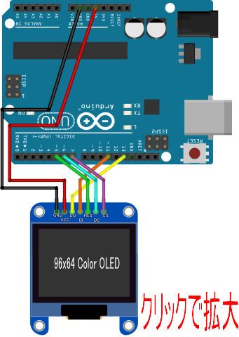
SSD1331のビットマップ
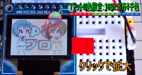
ドットの色は R(赤)5Bit、G(緑)6Bit、B(青)5Bitの16Bitで指定
ドットの並びはRemap & Color Depth settingコマンド(0xA0)で指定
| Remap & Color Depth setting(0XA0)コマンドのパラメタと表示方向 | |
|---|---|
| 設定値:Bxx100x00 A[5]=0, Disable COM Split Odd Even A[4]=0, Scan from COM 0 to COM [N –1] A[3]=0, Disable left-right swapping on COM A[1]=0, RAM Column 0 to 95 maps to Pin Seg A[0]=0, Horizontal address increment 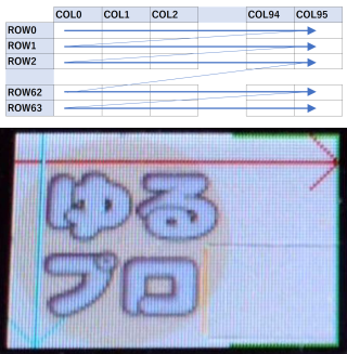 |
設定値:Bxx110x10 A[5]=1, Enable COM Split Odd Even A[4]=1, Scan from COM [N-1] to COM0. A[3]=0, Disable left-right swapping on COM A[1]=1, RAM Column 0 to 95 maps to Pin Seg A[0]=0, Horizontal address increment 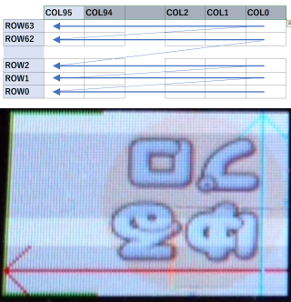 |
| 設定値:Bxx100x00 A[5]=0, Disable COM Split Odd Even A[4]=0, Scan from COM 0 to COM [N –1] A[3]=0, Disable left-right swapping on COM A[1]=0, RAM Column 0 to 95 maps to Pin Seg A[0]=0, Horizontal address increment 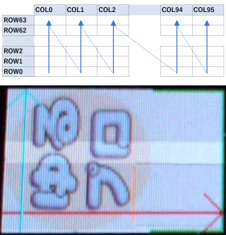 |
設定値:Bxx110x01 A[5]=1, Enable COM Split Odd Even A[4]=1, Scan from COM [N-1] to COM0. A[3]=0, Disable left-right swapping on COM A[1]=0, RAM Column 0 to 95 maps to Pin Seg A[0]=1, Vertical address increment 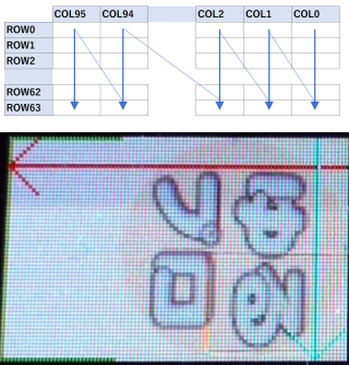 |
| Remap & Color Depth setting(0XA0)コマンドのパラメタとドットデータのフォーマット |
|---|
設定値:B00xxxxxx |
設定値:B01xxxxxx |
設定値:B10xxxxxx |
BITMAPデータの作成
Windows用の画像データをLCD用のBITMAP定義データに変換するツール LCD Image Converter を利用します。
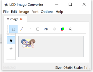 |
96x64にリサイズしたImageファイルを読み込みます。 トリミングと拡大は読み込み後にも操作できます。 |
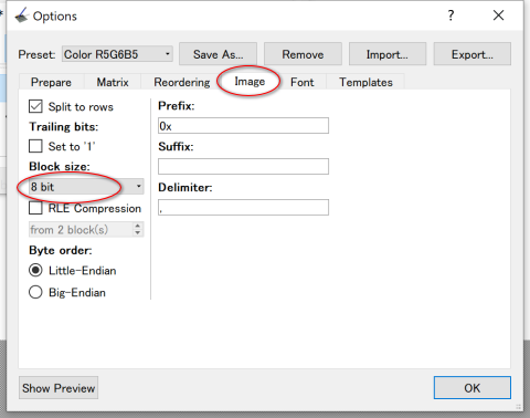 |
Optionsを開いて作成するイメージの BlockSizeを8Bitに設定 |
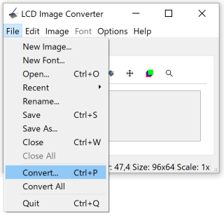 |
コンバートを実行 |
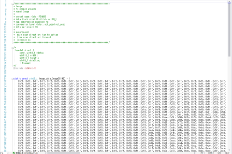 |
イメージデータの定義ファイルが出来るので スケッチに貼付けて使用できます。 |
