PICO LCD-1.8 (ST7735S)
Raspberry Pi Pico用 1.8インチ 液晶モジュール 160×128 (ST7735S) のArduinoIDEでの使用方法RaspberryPi PICOと連結して使用する設計になっているため、SPIピン(SLCK/MOSI)がGP10/GP11に固定になっていて変更できません。
ArduinoIDEでは(2022.02)現状、SPIピン(SLCK/MOSI)はGP2/GP3に固定になっており、普通の方法では、このLCDは使用できません。
1) 変換コネクタを使ってSPIピン(SLCK/MOSI)をGP2/GP3に変更する。
2) SoftwareSPIを使用する
3) ArduinoIDE以外の方法(Pythonとか)でプログラミング
の、いずれかの方法になります。
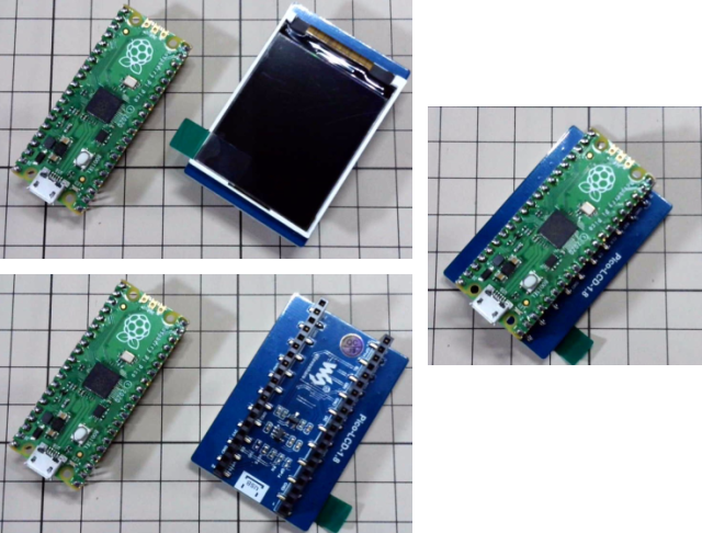
使用するピン
コネクタは40ピン付いていますが、実際に使用されているのは▼の8本です。| RaspberryPi PICOと合体して使用する場合 | ||
|---|---|---|
| 物理ピン番号 | 論理ピン名 | 機能 |
| 11 | GP8 | Data/Command |
| 12 | GP9 | Slave Selec |
| 14 | GP10 | CLK |
| 15 | GP11 | MOSI |
| 16 | GP12 | Reset |
| 17 | GP13 | BackLight |
| 39 | VSYS | 1.8~5.5V |
| 38 | GND | GND |
| RaspberryPi PICO+ArduinoIDEで使用する場合 | ||
|---|---|---|
| 物理ピン番号 | 論理ピン名 | 機能 |
| 11 | GP8 | Data/Command |
| 12 | GP9 | Slave Selec |
| 4 | GP2 | CLK |
| 5 | GP3 | MOSI |
| 16 | GP12 | Reset |
| 17 | GP13 | BackLight |
| 39 | VSYS | 1.8~5.5V |
| 38 | GND | GND |
GP10をGP2に、GP11をGP3に差し替えれば、ArduinoIDEで普通にSPIデバイスとして使用できます。
※ ▼はAdafruit_ST7735_and_ST7789_Libraryのサンプルスケッチを使用
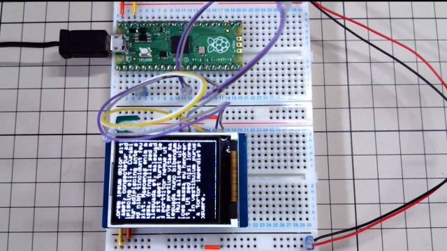
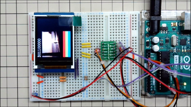
ArduinoUNOでs使用する場合にはレベルシフターか抵抗を使って、信号レベルを3.3Vに落とした方が良い模様
| ArduinoUNOで使用する場合 | |
|---|---|
| 論理ピン名 | 機能 |
| 任意 | Data/Command |
| D10 ※変更可 | Slave Selec |
| D13 | CLK |
| D11 | MOSI |
| 任意 | Reset |
| 任意 | BackLight |
| 5V | 5.0V |
| GND | GND |
ST7735Sのコマンド
コマンドは1バイトでパラメタは全てデータ扱いのため、コマンド送信時にはD/CをLOWに、パラメタ送信時にはD/CをHIGHにする。
| コマンド送信手順 | |
|---|---|
| SS(Slave Select) | LOWにする |
| DC(Data/Command) | LOWにする |
| コマンド送信 | |
| DC(Data/Command) | HIGHにする |
| パラメタ送信 | |
| SS(Slave Select) | HIGHにする |
▼ 必要最低限のコマンド。他にも色調整関連のコマンドが多数あります。詳細はST7735Sのスペックシート参照。
| コマンド | パラメタ | 動作 |
|---|---|---|
| 0x01 | SOFTWARE RESET | |
| 0x11 | Sleep Out | |
| 0x13 | NomalDisplayMode | |
| 0x20 | Display Inversion Off | |
| 0x28 | Display OFF | |
| 0x29 | Display ON | |
| 0x36 | 1Byte | スキャン方向 |
| 0x3A | 0x05 | 16Bit Pixel Mode |
| 0xB4 | 0x00 | 表示色反転モード |
| 0xB6 | 0x15,0x02 | フレームレート設定 |
| コマンド | パラメタ | 動作 |
| 0x2A | 開始X上位バイト、開始X下位バイト、終了X上位バイト、終了X下位バイト (0~159の範囲なので上位バイトは0固定で良い気がする) |
Colmun Address |
| 0x2B | 開始Y上位バイト、開始Y下位バイト、終了Y上位バイト、終了Y下位バイト (0~159の範囲なので上位バイトは0固定で良い気がする) |
Row Address |
| 0x2C | データ | BitmapData |
描画モード設定コマンド Memory Data Access Control (0x36)
| D7 | D6 | D5 | D4 | D3 | D2 | D1 | D0 | |
|---|---|---|---|---|---|---|---|---|
| コマンド | 0 | 0 | 1 | 1 | 0 | 1 | 1 | 0 |
| パラメタ | MY (Y軸方向) |
MX (X軸方向) |
MV (XY軸入れ替え) |
ML (Y軸更新方向) |
RGB (色割り当て RGB or BGR) |
MH (X軸更新方向) |
- | - |
ML/RGB/MHは変更する必要はあまりないと思われる。
MY/MX/MVの組み合わせによる表示方向は▼のようになる
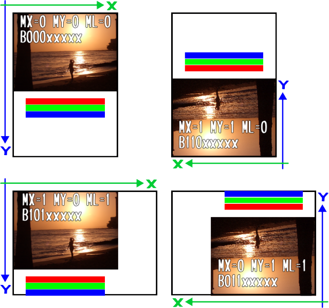
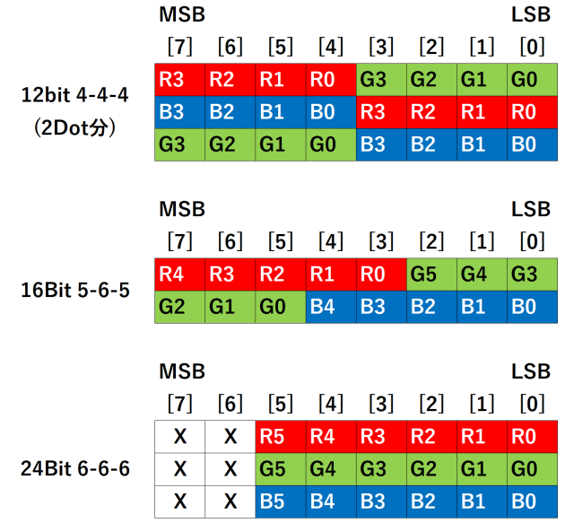
Dot指定方法設定コマンド Interface Pixel Format(0x3A)
1Dot(ピクセル)の色を指定する方法(フォーマット)を指定するこの指定で、描画コマンド Column Address Set (0x2A) のパラメタの意味が変わる
| D7 | D6 | D5 | D4 | D3 | D2 | D1 | D0 | |
|---|---|---|---|---|---|---|---|---|
| コマンド | 0 | 0 | 1 | 1 | 1 | 0 | 1 | 0 |
| パラメタ | - | - | - | - | - | IFPF2 | IFPF1 | IFPF0 |
| IFPF[2:0] | HEX | Color Format |
|---|---|---|
| 011 | 3 | 12-bit/pixel |
| 101 | 5 | 16-bit/pixel |
| 110 | 6 | 18-bit/pixel |
| 111 | 7 | No used |
描画手順
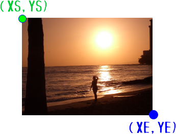
描画範囲を指定し、指定範囲を埋めるBitmapデータを送信する| 描画範囲 COLの指定 | 0X2A | 0,XS,0,XE |
|---|---|---|
| 描画範囲 ROWの指定 | 0x2B | 0,YS,0xYE |
| 描画データ送信 | 0x2C | Bitmapデータ |
※ <>を全角<>に置き換えています。コピペの際は注意してください(ZIPファイルの解凍を推奨)。
#include <SPI.h>
#include "image2.h"
#include "font8x16.h"

#define TFT_CS  9    // Data/Command
#define TFT_DC  8    // Data/Command
#define TFT_RST 12   // RESET
#define TFT_BL  13   // BACK LIGHT

#define TFT_WIDTH 160
#define TFT_HIGH  128
uint8_t SPIBuf[256] ;   // SPI転送用バッファ
uint8_t fontColorF[2] ; // TEXT FOR GROND COLOR
uint8_t fontColorB[2] ; // TEXT BACK GROND COLOR

char str[64] ;

SPISettings settings = SPISettings(32000000, MSBFIRST, SPI_MODE0);

// TFTにコマンドを送信
void tftSendCommand(uint8_t command) {
  digitalWrite(TFT_CS, LOW); //
  digitalWrite(TFT_DC, LOW); // Command mode
  SPI.transfer(command);
  digitalWrite(TFT_CS, HIGH);  //
}

// TFTにコマンド+1バイトデータを送信
void tftSendCommand1(uint8_t command, uint8_t data1) {
  digitalWrite(TFT_CS, LOW); //
  digitalWrite(TFT_DC, LOW); // Command mode
  SPI.transfer(command);
  digitalWrite(TFT_DC, HIGH); // Command mode
  SPI.transfer(data1);
  digitalWrite(TFT_CS, HIGH);  //
}

// TFTにコマンド+2バイトデータを送信
void tftSendCommand2(uint8_t command, uint8_t data1, uint8_t data2) {
  digitalWrite(TFT_CS, LOW); //
  digitalWrite(TFT_DC, LOW); // Command mode
  SPI.transfer(command);
  digitalWrite(TFT_DC, HIGH); // Command mode
  SPI.transfer(data1);
  SPI.transfer(data2);
  digitalWrite(TFT_CS, HIGH);  //
}

// TFTにコマンド+3バイトデータを送信
void tftSendCommand3(uint8_t command, uint8_t data1, uint8_t data2, uint8_t data3) {
  digitalWrite(TFT_CS, LOW); //
  digitalWrite(TFT_DC, LOW); // Command mode
  SPI.transfer(command);
  digitalWrite(TFT_DC, HIGH); // Command mode
  SPI.transfer(data1);
  SPI.transfer(data2);
  SPI.transfer(data3);
  digitalWrite(TFT_CS, HIGH);  //
}

// TFTにコマンド+4バイトデータを送信
void tftSendCommand4(uint8_t command, uint8_t data1, uint8_t data2, uint8_t data3, uint8_t data4) {
  digitalWrite(TFT_CS, LOW); //
  digitalWrite(TFT_DC, LOW); // Command mode
  SPI.transfer(command);
  digitalWrite(TFT_DC, HIGH); // Command mode
  SPI.transfer(data1);
  SPI.transfer(data2);
  SPI.transfer(data3);
  SPI.transfer(data4);
  digitalWrite(TFT_CS, HIGH);  //
}

// 画面クリア
void cls(bool rot) {
  if (rot) {
    tftSendCommand4(0x2A,0,0,0,131) ; // Colmun Address
    tftSendCommand4(0x2B,0,0,0,161) ; // Row Address
  } else {
    tftSendCommand4(0x2A,0,0,0,160) ; // Colmun Address
    tftSendCommand4(0x2B,0,0,0,131) ; // Row Address
  }

  digitalWrite(TFT_CS, LOW);
  digitalWrite(TFT_DC, LOW); // Command mode
  SPI.transfer(0x2C);
  digitalWrite(TFT_DC, HIGH); // Data mode
  for (int i=0;i<160;i++) {
    for (int j=0;j<131;j++) {
      SPI.transfer(B00000000);
      SPI.transfer(B00000000);
    }
  }
  digitalWrite(TFT_DC, LOW); // Command mode
  digitalWrite(TFT_CS, HIGH);  //
}

// 塗りつぶし
void fill(int xs,int ys , int xe,int ye , uint8_t c1 , uint8_t c2) {
  tftSendCommand4(0x2A,0,xs,0,xe) ; // Colmun Address
  tftSendCommand4(0x2B,0,ys,0,ye) ; // Row Address

  digitalWrite(TFT_CS, LOW);
  digitalWrite(TFT_DC, LOW); // Command mode
  SPI.transfer(0x2C);
  digitalWrite(TFT_DC, HIGH); // Data mode
  for (int i=0;i<xe-xs+1;i++) {
    for (int j=0;j<ye-ys+1;j++) {
      uint8_t dw = c1 ;
      SPI.transfer(dw);
      dw = c2 ;
      SPI.transfer(dw);
    }
  }
  digitalWrite(TFT_DC, LOW); // Command mode
  digitalWrite(TFT_CS, HIGH);  //
}

// BITマップ表示
void drowBitMap(int offsetX , int offsetY , int width, int hight, uint8_t bitMap[]) {
  uint8_t endX = offsetX + width - 1;
  uint8_t endY = offsetY + hight - 1;
  tftSendCommand4(0x2A,0,offsetX,0,endX) ; // Colmun Address
  tftSendCommand4(0x2B,0,offsetY,0,endY) ; // Row Address
  delayMicroseconds(500);

  int pos = 0 ;
  digitalWrite(TFT_CS, LOW);
  digitalWrite(TFT_DC, LOW); // Command mode
  SPI.transfer(0x2C);
  digitalWrite(TFT_DC, HIGH); // Data mode
  for (int row = 0 ; row < hight ; row ++) {
    // 表示データ転送
    // Arduinoだとメモリが足りなくて1画面分を一気に転送する事ができない
    // なので、1Lineずつ送信している
    for (int col = 0 ; col < width * 2 ; col ++ ) {
      SPIBuf[col] = bitMap[pos];
      //      SPIBuf[col] = 0xF8 ;
      pos ++ ;
    }
    SPI.transfer(SPIBuf, width * 2);
  }
  digitalWrite(TFT_DC, LOW); // Command mode
  digitalWrite(TFT_CS, HIGH);  //
}

void DrowFont(uint8_t code , uint8_t x, uint8_t y) {
  int pos = (code - 0x20) * 16 ;
  memset(SPIBuf,0,8*16*2) ;
  for (int i=0;i<16;i++) {
    uint8_t data = ssd1306xled_font8x16[pos + i];
    uint8_t bitMast = 0x01 ;
    for (int j=0;j<8;j++) {
      int fpos = 0 ;
      if (i<8) {
        fpos = (j*8+i)*2 ;
      } else {
        fpos = ((j+8)*8+(i-8))*2 ;
      }
      if ((data & bitMast) == 0) {
        SPIBuf[fpos] = fontColorB[0] ;
        SPIBuf[fpos+1] = fontColorB[1] ;
      } else {
        SPIBuf[fpos] = fontColorF[0] ;
        SPIBuf[fpos+1] = fontColorF[1] ;
      }
      bitMast <<= 1 ;
    }
  }

  uint8_t endX = x + 7 ;
  uint8_t endY = y + 15;

  tftSendCommand4(0x2A,0,x,0,endX) ; // Colmun Address
  tftSendCommand4(0x2B,0,y,0,endY) ; // Row Address
  digitalWrite(TFT_CS, LOW);
  digitalWrite(TFT_DC, LOW); // Command mode
  SPI.transfer(0x2C);
  digitalWrite(TFT_DC, HIGH); // Data mode
  SPI.transfer(SPIBuf, 8*16*2);
  digitalWrite(TFT_DC, LOW); // Command mode
  digitalWrite(TFT_CS, HIGH);  //
  delayMicroseconds(500);
}

void DrowStr(char str[] , uint8_t x , uint8_t y) {
  for (int i=0;str[i] != 0 ; i++) {
      DrowFont(str[i],x,y) ;
      x += 8 ;
      if (x+8>=96) {
        x = 0 ;
        y += 16 ;
        if (y + 16 >= 64) {
          y = 0 ;
        }
      }
  }
}

void setup() {
  Serial.begin(9600);
  Serial.print(F("Pico LCD-1.8 (ST3375)Test"));

  SPI.begin();  //SPIを初期化、SCK、MOSI、SSの各ピンの動作は出力、SCK、MOSIはLOW、SSはHIGH
  SPI.beginTransaction(settings);

  // -----  ST3375 INITIAL -----
  pinMode(TFT_CS, OUTPUT);
  pinMode(TFT_DC, OUTPUT);
  pinMode(TFT_BL, OUTPUT);
  pinMode(TFT_RST, OUTPUT);

  // BACK LIGHT ON
  digitalWrite(TFT_BL, HIGH);

  // --- HARD Ware Reset
  digitalWrite(TFT_RST, HIGH);
  delay(500);                  // VDD goes high at start, pause for 500 ms
  digitalWrite(TFT_RST, LOW);  // Bring reset low
  delay(100);                  // Wait 100 ms
  digitalWrite(TFT_RST, HIGH); // Bring out of reset
  delay(500);                  // Wait 500 ms, more then 120 ms
  // --- SOFT Ware Reset
  tftSendCommand(0x01) ;       // SOFTWARE RESET
  delay(50);

  // --- Initial Comands
  bool r = false ;
  tftSendCommand(0x28) ;            // Display OFF : 0x29 - Display ON
  delay(500);

  tftSendCommand(0x11) ;            // Sleep Out
  delay(500);
  tftSendCommand1(0x3A,05) ;        // 16Bit Pixel Mode
  delay(10);
  tftSendCommand1(0x36,B10100000) ; r = false; // MX MY MV ML RGB MH x x:横向き1
//  tftSendCommand1(0x36,B01100000) ; r = false;  // MX MY MV ML RGB MH x x:横向き2
//  tftSendCommand1(0x36,B00000000) ; r = true;  // MX MY MV ML RGB MH x x:縦向き1
//  tftSendCommand1(0x36,B11000000) ; r = true;  // MX MY MV ML RGB MH x x:縦向き2(多分これがスタンダード)
  tftSendCommand2(0xB6,0x15,0x02) ; // Display settings #5
  tftSendCommand1(0xB4,0x00) ;      // Display inversion control

  tftSendCommand(0x13) ;            // NomalDisplayMode
  tftSendCommand(0x20) ;            // Display Inversion Off

  // ---
  cls(r) ;
  delay(500);
  tftSendCommand(0x29) ;            // Display ON : 0x28 - Display OFF
  delay(500);
}

// the loop function runs over and over again forever
void loop() {
  bool r = false ;
  fontColorB[0] = 0x00 ; fontColorB[1] = 0x00 ; // TEXT BACK GROND COLOR
  fontColorF[0] = 0xFF ; fontColorF[1] = 0xFF ; // TEXT FOR GROND COLOR - WHITE
  for (int i=0;i<4;i++) {
    switch(i) {
      case  0:
        sprintf(str,"B10100000");
        tftSendCommand1(0x36,B10100000) ;// MX MY MV ML RGB MH x x:横向き1
        r = false;
        break ;
      case  1:
        sprintf(str,"B01100000");
        tftSendCommand1(0x36,B01100000) ; // MX MY MV ML RGB MH x x:横向き2
        r = false;
        break ;
      case  2:
        sprintf(str,"B00000000");
        tftSendCommand1(0x36,B00000000) ; // MX MY MV ML RGB MH x x:縦向き1
        r = true;
        break ;
      case  3:
        sprintf(str,"B11000000");
        tftSendCommand1(0x36,B11000000) ; // MX MY MV ML RGB MH x x:縦向き2(多分これがスタンダード)
        r = true;
        break ;
    }
    cls(r) ;
    DrowStr(str,10,0) ;
    drowBitMap(10,20,96,64,bitmapData2) ;
    fill(10, 90,106, 99,B11111000,B00000000) ;
    fill(10,102,106,111,B00000111,B11100000) ;
    fill(10,113,106,122,B00000000,B00011111) ;
    delay(5000);
 }
}
BITMAPデータの作成
Windows用の画像データをLCD用のBITMAP定義データに変換するツール LCD Image Converter を利用します。
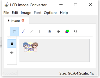 |
96x64にリサイズしたImageファイルを読み込みます。 トリミングと拡大は読み込み後にも操作できます。 |
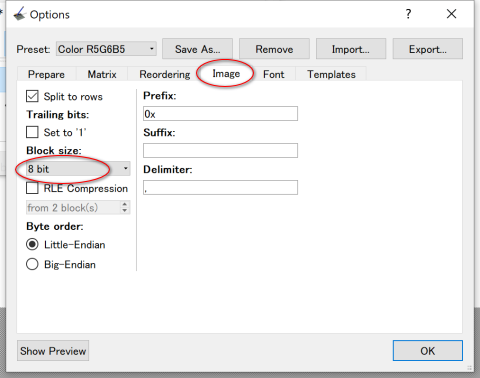 |
Optionsを開いて作成するイメージの BlockSizeを8Bitに設定 |
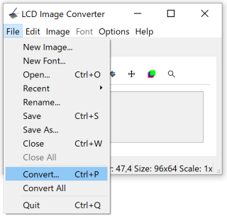 |
コンバートを実行 |
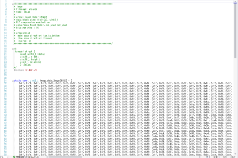 |
イメージデータの定義ファイルが出来るので スケッチに貼付けて使用できます。 |
