240x240 カラーTFT液晶 ST7789

240x240 ドット表示のカラーTFT液晶です。
PICO LCD-1.8(ST7735S)の姉妹品と思われます。
操作方法はST7735Sと共通しています。
※一部互換性のないコマンドがあるので注意
←のユニットにはCSピンがありません。
SPIにコレ1個しか接続できないので注意。
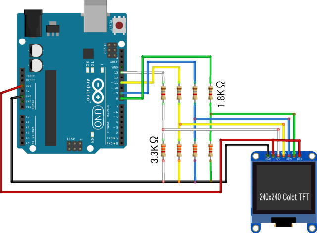
ArduinoUNOとの接続
電源、信号レベル共に3.3VなのでArduinoUNOで使用する場合には信号レベル変換が必要です。レベルコンバータが必要ですが・・・MISOピンがなく、ArduinoからST7789への一方通行なので抵抗を使って分圧したら動きました。
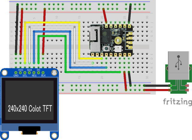
M5Stamp PICOとの接続
M5Stamp PICOは信号レベルが3.3Vなので直接接続できます。電源とバックライトも3.3Vなので電源電圧には注意
ST7789のコマンド
コマンドは1バイトでパラメタは全てデータ扱いのため、コマンド送信時にはD/CをLOWに、パラメタ送信時にはD/CをHIGHにする。
| コマンド送信手順 | |
|---|---|
| SS(Slave Select) | LOWにする |
| DC(Data/Command) | LOWにする |
| コマンド送信 | |
| DC(Data/Command) | HIGHにする |
| パラメタ送信 | |
| SS(Slave Select) | HIGHにする |
▼ 必要最低限のコマンド。他にも色調整関連のコマンドが多数あります。詳細はST7735Sのスペックシート参照。
| コマンド | パラメタ | 動作 |
|---|---|---|
| 0x01 | SOFTWARE RESET | |
| 0x11 | Sleep Out | |
| 0x13 | NomalDisplayMode | |
| 0x21 | Display Inversion Off | |
| 0x28 | Display OFF | |
| 0x29 | Display ON | |
| 0x36 | 1Byte | スキャン方向 |
| 0x3A | 0x05 | 16Bit Pixel Mode |
| 0xB4 | 0x00 | 表示色反転モード |
| 0xB6 | 0x15,0x02 | フレームレート設定 |
| コマンド | パラメタ | 動作 |
| 0x37 | 開始X上位バイト、開始X下位バイト | 表示開始ライン |
| 0x2A | 開始X上位バイト、開始X下位バイト、終了X上位バイト、終了X下位バイト | Colmun Address |
| 0x2B | 開始Y上位バイト、開始Y下位バイト、終了Y上位バイト、終了Y下位バイト | Row Address |
| 0x2C | データ | BitmapData |
描画モード設定コマンド Memory Data Access Control (0x36)
| D7 | D6 | D5 | D4 | D3 | D2 | D1 | D0 | |
|---|---|---|---|---|---|---|---|---|
| コマンド | 0 | 0 | 1 | 1 | 0 | 1 | 1 | 0 |
| パラメタ | MY (Y軸方向) |
MX (X軸方向) |
MV (XY軸入れ替え) |
ML (Y軸更新方向) |
RGB (色割り当て RGB or BGR) |
MH (X軸更新方向) |
- | - |
ML/RGB/MHは変更する必要はあまりないと思われる。
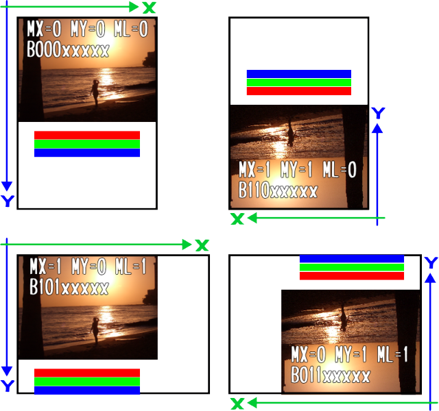
MY/MX/MVの組み合わせによる表示方向は▼のようになる
Dot指定方法設定コマンド Interface Pixel Format(0x3A)
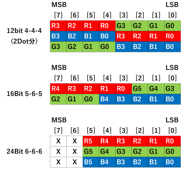
1Dot(ピクセル)の色を指定する方法(フォーマット)を指定するこの指定で、描画コマンド Column Address Set (0x2A) のパラメタの意味が変わる
| D7 | D6 | D5 | D4 | D3 | D2 | D1 | D0 | |
|---|---|---|---|---|---|---|---|---|
| コマンド | 0 | 0 | 1 | 1 | 1 | 0 | 1 | 0 |
| パラメタ | - | - | - | - | - | IFPF2 | IFPF1 | IFPF0 |
| IFPF[2:0] | HEX | Color Format |
|---|---|---|
| 011 | 3 | 12-bit/pixel |
| 101 | 5 | 16-bit/pixel |
| 110 | 6 | 18-bit/pixel |
| 111 | 7 | No used |
描画手順
描画範囲を指定し、指定範囲を埋めるBitmapデータを送信する| 描画範囲 COLの指定 | 0X2A | 0,XS,0,XE |
|---|---|---|
| 描画範囲 ROWの指定 | 0x2B | 0,YS,0xYE |
| 描画データ送信 | 0x2C | Bitmapデータ |
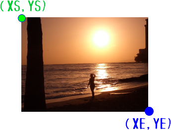
※ <>を全角<>に置き換えています。コピペの際は注意してください。
▼に表示しているのは、プログラムの一部です。全体はZIPファイルを解凍して参照してください。
#include <SPI.h>
#include "image.h"
#include "font8x16.h"

#define TFT_DC  8   // Data/Command
#define TFT_RST 9   // RESET

#define TFT_WIDTH 240
#define TFT_HIGH  320
uint8_t SPIBuf[320*2] ; // SPI転送用バッファ
uint8_t fontColorF[2] ; // TEXT FOR GROND COLOR
uint8_t fontColorB[2] ; // TEXT BACK GROND COLOR

#define HBYTE(u) ((u >> 8) & 0xFF)
#define LBYTE(u) (u & 0xFF)

#ifndef _swap_int16_t
#define _swap_int16_t(a, b) { int16_t t = a ; a = b; b = t; }
#endif

char str[64] ;
// SPISettings settings = SPISettings(16000000, MSBFIRST, SPI_MODE3);

// TFTにコマンドを送信
void tftSendCommand(uint8_t command) {
  digitalWrite(TFT_DC, LOW); // Command mode
  SPI.transfer(command);
}

// TFTにコマンド+1バイトデータを送信
void tftSendCommand1(uint8_t command, uint8_t data1) {
  digitalWrite(TFT_DC, LOW); // Command mode
  SPI.transfer(command);
  digitalWrite(TFT_DC, HIGH); // Command mode
  SPI.transfer(data1);
}

// TFTにコマンド+2バイトデータを送信
void tftSendCommand2(uint8_t command, uint8_t data1, uint8_t data2) {
  digitalWrite(TFT_DC, LOW); // Command mode
  SPI.transfer(command);
  digitalWrite(TFT_DC, HIGH); // Command mode
  SPI.transfer(data1);
  SPI.transfer(data2);
}

// TFTにコマンド+3バイトデータを送信
void tftSendCommand3(uint8_t command, uint8_t data1, uint8_t data2, uint8_t data3) {
  digitalWrite(TFT_DC, LOW); // Command mode
  SPI.transfer(command);
  digitalWrite(TFT_DC, HIGH); // Command mode
  SPI.transfer(data1);
  SPI.transfer(data2);
  SPI.transfer(data3);
}

// TFTにコマンド+4バイトデータを送信
void tftSendCommand4(uint8_t command, uint8_t data1, uint8_t data2, uint8_t data3, uint8_t data4) {
  digitalWrite(TFT_DC, LOW); // Command mode
  SPI.transfer(command);
  digitalWrite(TFT_DC, HIGH); // Command mode
  SPI.transfer(data1);
  SPI.transfer(data2);
  SPI.transfer(data3);
  SPI.transfer(data4);
}

// 画面クリア
void cls(bool rot) {
  if (rot) {
    tftSendCommand4(0x2A,0,0,0,239) ; // Colmun Address
    tftSendCommand4(0x2B,0,0,0x01,0x3F) ; // Row Address
  } else {
    tftSendCommand4(0x2A,0,0,0x01,0x3F) ; // Colmun Address
    tftSendCommand4(0x2B,0,0,0,239) ; // Row Address
  }
  digitalWrite(TFT_DC, LOW); // Command mode
  SPI.transfer(0x2C);
  digitalWrite(TFT_DC, HIGH); // Data mode
  for (int i=0;i<240;i++) {
    memset(SPIBuf,0,320*2) ;
    SPI.transfer(SPIBuf, 320*2);
  }
  digitalWrite(TFT_DC, LOW); // Command mode
  delay(10) ;
}

// 塗りつぶし
void fill(int xs,int ys , int xe,int ye , uint8_t c1 , uint8_t c2) {
  uint8_t xsH = HBYTE(xs) ;
  uint8_t xsL = LBYTE(xs) ;
  uint8_t ysH = HBYTE(ys) ;
  uint8_t ysL = LBYTE(ys) ;
  uint8_t xeH = HBYTE(xe) ;
  uint8_t xeL = LBYTE(xe) ;
  uint8_t yeH = HBYTE(ye) ;
  uint8_t yeL = LBYTE(ye) ;
  tftSendCommand4(0x2A,xsH,xsL,xeH,xeL) ; // Colmun Address
  tftSendCommand4(0x2B,ysH,ysL,yeH,yeL) ; // Row Address
  digitalWrite(TFT_DC, LOW); // Command mode
  SPI.transfer(0x2C);
  digitalWrite(TFT_DC, HIGH); // Data mode
  int w = ye-ys+1 ;
  for (int i=0;i<xe-xs+1;i++) {
    for (int col = 0 ; col < w * 2 ; col +=2 ) {
      SPIBuf[col] = c1 ;
      SPIBuf[col+1] = c2 ;
    }
    SPI.transfer(SPIBuf, w * 2);
  }
  digitalWrite(TFT_DC, LOW); // Command mode
  delay(5) ;
}

// BITマップ表示
void drowBitMap(int offsetX , int offsetY , int width, int hight, uint8_t bitMap[]) {
  uint8_t endX = offsetX + width - 1;
  uint8_t endY = offsetY + hight - 1;

  uint8_t xsH = HBYTE(offsetX) ;
  uint8_t xsL = LBYTE(offsetX) ;
  uint8_t xeH = HBYTE(endX) ;
  uint8_t xeL = LBYTE(endX) ;
  uint8_t ysH = HBYTE(offsetY) ;
  uint8_t ysL = LBYTE(offsetY) ;
  uint8_t yeH = HBYTE(endY) ;
  uint8_t yeL = LBYTE(endY) ;

  tftSendCommand4(0x2A,xsH,xsL,xeH,xeL) ; // Colmun Address
  tftSendCommand4(0x2B,ysH,ysL,yeH,yeL) ; // Row Address

  int pos = 0 ;
  digitalWrite(TFT_DC, LOW); // Command mode
  SPI.transfer(0x2C);
  digitalWrite(TFT_DC, HIGH); // Data mode
  for (int row = 0 ; row < hight ; row ++) {
    // 表示データ転送
    // Arduinoだとメモリが足りなくて1画面分を一気に転送する事ができない
    // なので、1Lineずつ送信している
    for (int col = 0 ; col < width * 2 ; col ++ ) {
      SPIBuf[col] = pgm_read_byte(bitMap + pos);
      pos ++ ;
    }
    SPI.transfer(SPIBuf, width * 2);
  }
  digitalWrite(TFT_DC, LOW); // Command mode
}

// 文字フォント表示
void DrowFont(uint8_t code , uint8_t x, uint8_t y) {
  int pos = (code - 0x20) * 16 ;
  memset(SPIBuf,0,8*16*2) ;
  for (int i=0;i<16;i++) {
    uint8_t data = pgm_read_byte(ssd1306xled_font8x16 + pos + i);
    uint8_t bitMast = 0x01 ;
    for (int j=0;j<8;j++) {
      int fpos = 0 ;
      if (i<8) {
        fpos = (j*8+i)*2 ;
      } else {
        fpos = ((j+8)*8+(i-8))*2 ;
      }
      if ((data & bitMast) == 0) {
        SPIBuf[fpos] = fontColorB[0] ;
        SPIBuf[fpos+1] = fontColorB[1] ;
      } else {
        SPIBuf[fpos] = fontColorF[0] ;
        SPIBuf[fpos+1] = fontColorF[1] ;
      }
      bitMast <<= 1 ;
    }
  }

  uint8_t endX = x + 7 ;
  uint8_t endY = y + 15;
  uint8_t xsH = HBYTE(x) ;
  uint8_t xsL = LBYTE(x) ;
  uint8_t xeH = HBYTE(endX) ;
  uint8_t xeL = LBYTE(endX) ;
  uint8_t ysH = HBYTE(y) ;
  uint8_t ysL = LBYTE(y) ;
  uint8_t yeH = HBYTE(endY) ;
  uint8_t yeL = LBYTE(endY) ;
  tftSendCommand4(0x2A,xsH,xsL,xeH,xeL) ; // Colmun Address
  tftSendCommand4(0x2B,ysH,ysL,yeH,yeL) ; // Row Address
  digitalWrite(TFT_DC, LOW); // Command mode
  SPI.transfer(0x2C);
  digitalWrite(TFT_DC, HIGH); // Data mode
  SPI.transfer(SPIBuf, 8*16*2);
  digitalWrite(TFT_DC, LOW); // Command mode
  delay(2) ;
}

// 文字列表示
void DrowStr(char str[] , uint8_t x , uint8_t y) {
  for (int i=0;str[i] != 0 ; i++) {
      DrowFont(str[i],x,y) ;
      x += 8 ;
      if (x+8>=TFT_HIGH) {
        x = 0 ;
        y += 16 ;
        if (y + 16 >= TFT_WIDTH) {
          y = 0 ;
        }
      }
  }
}

// ▼▼▼▼▼▼ Adafruit_GFX_Libraryからパクった描画関数
// ローテーションなし、Windowクリップなし、描画フレームへなしにして不要部分を削ってます

// 1Dot描画
void drawPixel(uint16_t x, uint16_t y, uint8_t color1,uint8_t color2) {
  if (x < 0 || x >= TFT_WIDTH || y < 0 || y >= TFT_HIGH) return ;

  int xe = x + 1 ;
  int ye = y + 1 ;

  uint8_t xsH = HBYTE(x) ;
  uint8_t xsL = LBYTE(x) ;
  uint8_t xeH = HBYTE(xe) ;
  uint8_t xeL = LBYTE(xe) ;
  uint8_t ysH = HBYTE(y) ;
  uint8_t ysL = LBYTE(y) ;
  uint8_t yeH = HBYTE(ye) ;
  uint8_t yeL = LBYTE(ye) ;
  digitalWrite(TFT_DC, LOW); // Command mode
  SPI.transfer(0x2A);
  digitalWrite(TFT_DC, HIGH); // Command mode
  SPI.transfer(xsH);
  SPI.transfer(xsL);
  SPI.transfer(xeH);
  SPI.transfer(xeL);

  digitalWrite(TFT_DC, LOW); // Command mode
  SPI.transfer(0x2B);
  digitalWrite(TFT_DC, HIGH); // Command mode
  SPI.transfer(ysH);
  SPI.transfer(ysL);
  SPI.transfer(yeH);
  SPI.transfer(yeL);

  digitalWrite(TFT_DC, LOW); // Command mode
  SPI.transfer(0x2C);
  digitalWrite(TFT_DC, HIGH); // Command mode
  SPI.transfer(color1);
  SPI.transfer(color2);
}

// Line描画
void drawLine(int x0, int y0, int x1, int y1, uint8_t color1,uint8_t color2) {
  int16_t steep = abs(y1 - y0) > abs(x1 - x0);
  if (steep) {
    _swap_int16_t(x0, y0);
    _swap_int16_t(x1, y1);
  }

  if (x0 > x1) {
    _swap_int16_t(x0, x1);
    _swap_int16_t(y0, y1);
  }

  int16_t dx, dy;
  dx = x1 - x0;
  dy = abs(y1 - y0);

  int16_t err = dx / 2;
  int16_t ystep;

  if (y0 < y1) {
    ystep = 1;
  } else {
    ystep = -1;
  }

  for (; x0 <= x1; x0++) {
    if (steep) {
      drawPixel(y0, x0, color1 , color2);
    } else {
      drawPixel(x0, y0, color1 , color2);
    }
    err -= dy;
    if (err < 0) {
      y0 += ystep;
      err += dx;
    }
  }
}

// 塗りつぶし矩形
void fillRect(int x, int y, int w, int h, uint8_t color1, uint8_t color2) {
  uint8_t endX = x + w - 1;
  uint8_t endY = y + h - 1;

  uint8_t xsH = HBYTE(x) ;
  uint8_t xsL = LBYTE(x) ;
  uint8_t xeH = HBYTE(endX) ;
  uint8_t xeL = LBYTE(endX) ;
  uint8_t ysH = HBYTE(y) ;
  uint8_t ysL = LBYTE(y) ;
  uint8_t yeH = HBYTE(endY) ;
  uint8_t yeL = LBYTE(endY) ;

  tftSendCommand4(0x2A,xsH,xsL,xeH,xeL) ; // Colmun Address
  tftSendCommand4(0x2B,ysH,ysL,yeH,yeL) ; // Row Address

  int pos = 0 ;
  digitalWrite(TFT_DC, LOW); // Command mode
  SPI.transfer(0x2C);
  digitalWrite(TFT_DC, HIGH); // Data mode
  for (int row = 0 ; row < h ; row ++) {
    // メモリが足りなくて1画面分を一気に転送する事ができない
    // なので、1Lineずつ送信している
    for (int col = 0 ; col < w * 2 ; col +=2 ) {
      SPIBuf[col] = color1 ;
      SPIBuf[col+1] = color2 ;
    }
    SPI.transfer(SPIBuf, w * 2);
  }
}

// 矩形
void drawRect(int16_t x, int16_t y, int16_t w, int16_t h, uint8_t color1, uint8_t color2) {
  int xe = x + w - 1 ;
  int ye = y + h - 1 ;
  drawLine(x, y, xe,y ,color1,color2);
  drawLine(x, y, x ,ye,color1,color2);
  drawLine(xe,y, xe,ye,color1,color2);
  drawLine(x ,ye,xe,ye,color1,color2);
}

// 円
void drawCircle(int16_t x0, int16_t y0, int16_t r, uint8_t color1, uint8_t color2) {
  int16_t f = 1 - r;
  int16_t ddF_x = 1;
  int16_t ddF_y = -2 * r;
  int16_t x = 0;
  int16_t y = r;

  drawPixel(x0, y0 + r, color1,color2);
  drawPixel(x0, y0 - r, color1,color2);
  drawPixel(x0 + r, y0, color1,color2);
  drawPixel(x0 - r, y0, color1,color2);

  while (x < y) {
    if (f >= 0) {
      y--;
      ddF_y += 2;
      f += ddF_y;
    }
    x++;
    ddF_x += 2;
    f += ddF_x;

    drawPixel(x0 + x, y0 + y, color1,color2);
    drawPixel(x0 - x, y0 + y, color1,color2);
    drawPixel(x0 + x, y0 - y, color1,color2);
    drawPixel(x0 - x, y0 - y, color1,color2);
    drawPixel(x0 + y, y0 + x, color1,color2);
    drawPixel(x0 - y, y0 + x, color1,color2);
    drawPixel(x0 + y, y0 - x, color1,color2);
    drawPixel(x0 - y, y0 - x, color1,color2);
  }
}

// 塗りつぶ円
void fillCircle(int16_t x0, int16_t y0, int16_t r,uint8_t color1, uint8_t color2) {
  int16_t f = 1 - r;
  int16_t ddF_x = 1;
  int16_t ddF_y = -2 * r;
  int16_t x = 0;
  int16_t y = r;
  int16_t px = x;
  int16_t py = y;
  int16_t delta = 1 ;

  fillRect(x0, y0 - r , 1 , r * 2 , color1,color2);

  while (x < y) {
    if (f >= 0) {
      y--;
      ddF_y += 2;
      f += ddF_y;
    }
    x++;
    ddF_x += 2;
    f += ddF_x;
    // These checks avoid double-drawing certain lines, important
    // for the SSD1306 library which has an INVERT drawing mode.
    if (x < (y + 1)) {
        fillRect(x0 + x , y0 - y , 1 , y * 2 + delta -1 , color1,color2);
        fillRect(x0 - x , y0 - y , 1 , y * 2 + delta -1 , color1,color2);
    }
    if (y != py) {
        fillRect(x0 + py , y0 - px , 1 , px * 2 + delta -1 , color1,color2);
        fillRect(x0 - py , y0 - px , 1 , px * 2 + delta -1 , color1,color2);
      py = y;
    }
    px = x;
  }
}

// 表示開始ライン設定
void dispStartLine(uint16_t y) {
  uint8_t yH = (y >> 8) & 0xFF ;
  uint8_t yL = y & 0xFF ;

  digitalWrite(TFT_DC, LOW); // Command mode
  SPI.transfer(0x37);
  digitalWrite(TFT_DC, HIGH); // Command mode
  SPI.transfer(yH);
  SPI.transfer(yL);
}

// ▲▽▲▽▲▽▲▽▲▽▲▽▲▽▲▽▲▽▲▽
// 初期設定
void setup() {
  Serial.begin(9600);
  Serial.print(F("ST3389 Test"));

  SPI.begin();  //SPIを初期化、SCK、MOSI、SSの各ピンの動作は出力、SCK、MOSIはLOW、SSはHIGH
  SPI.setClockDivider(SPI_CLOCK_DIV2);
  SPI.setBitOrder(MSBFIRST);
  SPI.setDataMode(SPI_MODE3);
//  SPI.beginTransaction(settings);

  // -----  ST3389 INITIAL -----
  pinMode(TFT_DC, OUTPUT);
  pinMode(TFT_RST, OUTPUT);

  // --- HARD Ware Reset
  digitalWrite(TFT_RST, HIGH);
  delay(500);                  // VDD goes high at start, pause for 500 ms
  digitalWrite(TFT_RST, LOW);  // Bring reset low
  delay(100);                  // Wait 100 ms
  digitalWrite(TFT_RST, HIGH); // Bring out of reset
  delay(500);                  // Wait 500 ms, more then 120 ms
  // --- SOFT Ware Reset
  tftSendCommand(0x01) ;       // SOFTWARE RESET
  delay(50);

  // --- Initial Comands
  bool r = false ;
  tftSendCommand(0x28) ;            // Display OFF : 0x29 - Display ON
  delay(500);

  tftSendCommand(0x11) ;            // Sleep Out
  delay(500);
  tftSendCommand1(0x3A,0x05) ;      // 16Bit Pixel Mode
  delay(10);
  tftSendCommand1(0x36,B00000000) ; r = false; // MX MY MV ML RGB MH x x:縦向き1
  tftSendCommand2(0xB6,0x15,0x02) ; // Display settings #5

  tftSendCommand(0x13) ;            // NomalDisplayMode
  tftSendCommand(0x21) ;            // Display Inversion Off

  // ---
  cls(r) ;
  delay(500);
  tftSendCommand(0x29) ;            // Display ON : 0x28 - Display OFF
  delay(500);
}

// ▲▽▲▽▲▽▲▽▲▽▲▽▲▽▲▽▲▽▲▽
// the loop function runs over and over again forever
void loop() {
  bool r = false ;
  int offsetX = 0 ;
  int offsetY = 0  ;
  fontColorB[0] = 0x00 ; fontColorB[1] = 0x00 ; // TEXT BACK GROND COLOR
  fontColorF[0] = 0xFF ; fontColorF[1] = 0xFF ; // TEXT FOR GROND COLOR - WHITE
  for (int i=0;i<4;i++) {
    switch(i) {
      case  0:
        sprintf(str,"B10100000");
        tftSendCommand1(0x36,B10100000) ;// MX MY MV ML RGB MH x x:横向き1
        r = false;
        offsetX = 80 ; offsetY = 0 ;
        break ;
      case  1:
        sprintf(str,"B01100000");
        tftSendCommand1(0x36,B01100000) ; // MX MY MV ML RGB MH x x:横向き2
        r = false;
        offsetX = 0 ; offsetY = 0 ;
        break ;
      case  2:
        sprintf(str,"B00000000");
        tftSendCommand1(0x36,B00000000) ; // MX MY MV ML RGB MH x x:縦向き1
        r = true;
        offsetX = 0 ; offsetY = 0 ;
        break ;
      case  3:
        sprintf(str,"B11000000");
        tftSendCommand1(0x36,B11000000) ; // MX MY MV ML RGB MH x x:縦向き2(多分これがスタンダード)
        r = true;
        offsetX = 0 ; offsetY = 80 ;
        break ;
    }
    cls(r) ;
    DrowStr(str,10+offsetX,offsetY) ;
    drowBitMap(10+offsetX,20+offsetY,100,75,bitmapData) ;
    fill(10+offsetX,100+offsetY,110+offsetX,109+offsetY,B11111000,B00000000) ;
    fill(10+offsetX,110+offsetY,110+offsetX,119+offsetY,B00000111,B11100000) ;
    fill(10+offsetX,120+offsetY,110+offsetX,129+offsetY,B00000000,B00011111) ;
    delay(2000);
  }

  // Graphics COMMAND
  tftSendCommand1(0x36,B00000000) ; // MX MY MV ML RGB MH x x:縦向き1

  int xs , ys , xe , ye , w , h ;
  int c ;
  // -- rect
  cls(false) ;
  xs = 109 ;  ys = 109 ;  w = 20 ;  h = 20 ;
  for (int i=0;i<11;i++) {
    switch (i % 3) {
      case 0: drawRect(xs,ys,w,h,B11111000,B00000000) ; break ;
      case 1: drawRect(xs,ys,w,h,B00000111,B11100000) ; break ;
      case 2: drawRect(xs,ys,w,h,B00000000,B00011111) ; break ;
    }
    xs -= 10 ;    ys -= 10 ;
    w += 20 ;    h += 20 ;
  }
  delay(3000);

  // -- fillRect
  xs = 0 ;  ys = 0 ;  w = 240 ;  h = 240 ;
  for (int i=0;i<11;i++) {
    switch (i % 3) {
      case 0: fillRect(xs,ys,w,h,B11111000,B00000000) ; break ;
      case 1: fillRect(xs,ys,w,h,B00000111,B11100000) ; break ;
      case 2: fillRect(xs,ys,w,h,B00000000,B00011111) ; break ;
    }
    xs += 10 ;    ys += 10 ;
    w -= 20 ;    h -= 20 ;
  }
  delay(3000);

  // -- Circle
  cls(false) ;
  xs = 119 ;  ys = 119 ;  w = 10 ;
  for (int i=0;i<11;i++) {
    switch (i % 3) {
      case 0: drawCircle(xs,ys,w,B11111000,B00000000) ; break ;
      case 1: drawCircle(xs,ys,w,B00000111,B11100000) ; break ;
      case 2: drawCircle(xs,ys,w,B00000000,B00011111) ; break ;
    }
    w += 10 ;
  }
  delay(3000);

  // -- FillCircle
  xs = 119 ;  ys = 119 ;  w = 120 ;
  for (int i=0;i<11;i++) {
    switch (i % 3) {
      case 0: fillCircle(xs,ys,w,B11111000,B00000000) ; break ;
      case 1: fillCircle(xs,ys,w,B00000111,B11100000) ; break ;
      case 2: fillCircle(xs,ys,w,B00000000,B00011111) ; break ;
    }
    w -= 10 ;
  }
  delay(3000);

  // -- LINE
  cls(false) ;
  xs = 0 ;  ys = 0 ;  xe = 0 ;  ye = 319 ;
  for (int i=0;i<24;i++) {
    drawLine(xs,ys,xe,ye,B11111000,B00000000) ;
    ys += 13 ;
    xe += 10 ;
  }

  xs = 0 ;  ys = 319 ;  xe = 239 ;  ye = 319 ;
  for (int i=0;i<24;i++) {
    drawLine(xs,ys,xe,ye,B00000111,B11100000) ;
    xs += 10 ;
    ye -= 13 ;
  }

  xs = 0 ;  ys = 0 ;  xe = 239 ;  ye = 0 ;
  for (int i=0;i<24;i++) {
    drawLine(xs,ys,xe,ye,B00000000,B00011111) ;
    xs += 10 ;
    ye += 13 ;
  }

  xs = 0 ;  ys = 319 ;  xe = 0 ;  ye = 0 ;
  for (int i=0;i<24;i++) {
    drawLine(xs,ys,xe,ye,B11111111,B11111111) ;
    ys -= 13 ;
    xe += 10 ;
  }
  delay(3000);

  // -- SCROLL
  for (int s=0;s<320;s++) {
    dispStartLine(s);
    delay(10);
  }
  delay(1000);
  for (int s=320;s>=0;s--) {
    dispStartLine(s);
    delay(10);
  }
  delay(1000);

  dispStartLine(0);
  delay(1000);
}
